


40k
LearnersWeekend/WeekdayLive
Class
- 2 Live Project
- Self-Paced/ Classroom
- Certification Pass Guaranteed
Learn how to use SP3D software for pipe designing. Enroll today to learn from an SP3D expert.
In collaboration with

Online/Offline
Format
LMS
Life Time Access
we train you to get hired.

Fundamental knowledge of engineering sketches and plans.
Knowledge of CAD software.
Experience in plant design concepts will be an advantage but is not obligatory.
Desire to acquire new skills and adjust to changes in technology.
Engineering experts who want to improve their plant design skills
CAD designers who intend to focus on SP3D
Fresh graduates looking for a career in plant design and engineering
People who have decided to change jobs that are related to SP3D
Project managers and team leaders who are striving to simplify the plant design processes
Creating and handling SP3D projects
Designing and engineering of plant layouts and piping systems
Generating detailed 3D models by using SP3D tools
Using SP3D, interacting with other stakeholders
SP3D Designer: Develop 3D models and drawings for plant layouts, piping, and equipment in SmartPlant 3D software.
SP3D Engineer: Design, engineer, and deliver projects of complex plants in SP3D software, complying with the standards of the industry and regulations.
SP3D Consultant: Carry out technical support and assistance for the clients for SP3D-related services, training, and solutions.
Plant Design Engineer: Using SP3D software to design and develop plant layouts, piping, and equipment that ensure efficient and safe operation.
Piping Designer: Using SP3D software to generate piping designs and models that comply with industry standards and regulations.
3D Modeling Specialist: Make 3D models and drawings that are accurate for plant projects, using SP3D software and other relevant tools.
Design Coordinator: Overseeing design activities, making sure that the design requirements are accomplished and the projects are delivered on time as per budget.
SP3D Trainer: To give training and support to the clients and colleagues on SP3D software, making sure that they have the necessary skills to implement the projects efficiently.
CAD Designer: Using SP3D and other relevant tools to make plant projects' detailed CAD designs and models.
Engineering Designer: Create designs for plant projects and ensure that these are done using SP3D software and industry standards and regulations.
Making exact 3D models and sketches through SP3D
Working with the decision makers to make the fulfilment of the design needs possible
Performing design checks and confirming conformity to the regulations of the industry
Giving the customers technical support and training
Becoming familiar with the latest SP3D gadgets and methods
Oil and gas
Petrochemicals
Power generation
Chemical processing
Pharmaceuticals
EPC (engineering, procurement)
we train you to get hired.
we train you to get hired.
By registering here, I agree to Croma Campus Terms & Conditions and Privacy Policy
Overview
Layout
Session Template
Session File
Options
Common Views
Zoom Tool
Window Area
Refresh View
Active View Control
Rotate View
Looking at Surface
View Format
Surface Style Rules
System
Assembly
Spatial (Volume or Planes)
Logical Permission Group
Object Types
Properties
Control Points / Notes / Hyperlink
Distance
Minimum Distance between Objects
Angle
Label Editor
Electrical System
Cableways
Cable Tray / Conduit
Cables
Branch on a Run
Intersect to Branch
Branch using Pinpoint
Selecting a Component
Reference Position
Point Along option
Selecting Different Ports / Flip
Routing Cableway
Edit Straight Features
Edit End Features
Edit Cross Sections
Conduit System
Route Options
Insert Conduit Fittings
Placing Ducts using Cableway
Selecting Equipment
Selecting Cables
Defining Properties
Selecting Cableways
Defining Exit/Entry Point
Indian Electricity Rules
National Electrical Code of India (NEC)
National Building Code of India (NBC)
Applicable Standards issued by Bureau of Indian standards (BIS)
Institute of Electrical & Electronics Engineers (IEEE)
Regulations of Local Fire Authorities
Requirements Stipulated by Pollution Control Board for Noise & Air
Control Devices
Measuring Devices
Circuit Protection Devices
Transformers
Diesel Generators
Capacitors
Bus Ducts, Bus-bars, Cables (HT/LT) & Wires
Motors & Pumps
Luminaries – General & Emergency
Isolators & Socket Outlets
UPS/Inverter & Battery Banks
Earthing or Grounding
Lightning Arrestor
Panels (LT)/Switch Board/Motor control centers (MCC’s)/Final Distribution boards (DB’s)
Cable Trays, Trunking or Raceways, Conduits & Underground Pipes (Concrete/PVC)
Lighting Load – Internal & External
Utility Power Load
HVAC Loads like FCU’s, Fans etc
PHE & FF loads like Water transfer pumps, Booster pumps, Fire Fighting pumps, Jockey pumps etc
Lifts (Elevator) Load
Computer & Data Centre (Server) Loads for Office Building
ComponentNote (Type 1 Labels)
EndConnection (Connection Note and Nozzle Note Labels)
Misc Spec labels (Pipeline Header)
Weld List Labels
DrawingFrame (Title Block Labels)
AttributeMAP
Mapping Attributes to the Border
Fixed - Style 1
Variable - Style 2
User-Defined - Style 3
Various Material List Options
Material List Labels
Using your Own Border Template
Modifying Delivered Style xml File to Match
Bulk Loading the Style
Volume Drawings
Snapshot Drawings
Manual Drafting
Overview
Layout
Session Template
Session File
Options
Common Views
Zoom Tool
Window Area
Refresh View
Active View Control
Rotate View
Looking at Surface
View Format
Surface Style Rules
System
Assembly
Spatial (Volume or Planes)
Logical Permission Group
Object Types
Properties
Control Points / Notes / Hyperlink
Distance
Minimum Distance between Objects
Angle
Label Editor
Grids
Coordinate Systems
Smart Plant Structure
Grid Wizard
Placing Coordinate System
Modifying Grids
Adding Grid Planes
Rotated Coordinate Systems
Rotated Planes
Beams
Columns
Braces
Name Rule - Naming Rule
Parent System
Type Category
Type
Priority
Continuity
Cross section
Section Standard
Section Type
Section Name
Material
Grade
Angle
Cardinal Point
Place Member Ribbon Bar
Basic Sketch 2D Overview
Draw (Sketch 2D)
Sketch Method
Select an Opening from Catalogue
Footing Ribbon Bar
Property Page
Placement
Modifications
Rule-Based Offset
Assembly Connection Ribbon Bar
Base Plate
Splice
Fitted Assembly Connection
Corner Gusset Plates
Attributes
Generic Move Command
Pin Point
Point Along Tool
Frame Connection
Coincident Plane
Offset from Plane
Angle from Plane
Point/Normal Vector
Point Plane
ComponentNote (Type 1 Labels)
EndConnection (Connection Note and Nozzle Note Labels)
Misc Spec labels (Pipeline Header)
Weld List Labels
DrawingFrame (Title Block Labels)
AttributeMAP
Mapping Attributes to the Border
Fixed - Style 1
Variable - Style 2
User-Defined - Style 3
Various Material List Options
Material List Labels
Using your Own Border Template
Modifying Delivered Style xml File to Match
Bulk Loading the Style
Volume Drawings
Snapshot Drawings
Manual Drafting
Overview
Layout
Session Template
Session File
Options
Common Views
Zoom Tool
Window Area
Refresh View
Active View Control
Rotate View
Looking at Surface
View Format
Surface Style Rules
System
Assembly
Spatial (Volume or Planes)
Logical Permission Group
Object Types
Properties
Control Points / Notes / Hyperlink
Distance
Minimum Distance between Objects
Angle
Label Editor
Pipeline
Pipe Run
Features
Parts
Port
Path Leg
Connections
Define the Pipe Run Properties
Length Control Tool
Route Pipe Run with Pin Point
Angle Control Tool
Pipe Run Smart Step Ribbon Bar
Plane Lock Options
Default Turn Options
Selecting a Turn
Select Fitter Options
Delete Pipeline
Delete Pipe Run
Delete Feature
Connecting to End Feature
Connecting to Nozzles
Branch on Pipe Run
Intersect to Branch
Selecting a Component
Reference Position
Point Along option
Selecting Different Ports / Flip
Edit Straight Features
Edit End Features
Edit Run Change Features
Editing Features
Insert Split Ribbon Bar
Flow Direction
Insulation
Relation Tab
Offset Control Tool
Component by Tag
Piping Specialty
Instruments
Slope Format
Route Sloped Run
Turn Slope Lock On/Off
Flanged Spec
Modifying Flanged Pipe
Relative Tracking Mode
Retrieving PID
Routing from PID
Comparing Data
Updating Data
Insert Tap Command
Running Reports
Setting Local IFC
Running Local IFC
Standard Parametric/Non-Parametric
Equipment Placement
Modelling of Equipment using Primitive Shape
3rd Party software – SAT format (SolidEdge v-14)
Physical, Insulation, Maintenance
Piping Port
Ducting Port
Cableway Port
Conduit Port
Cable Port
Foundation Port
Equipment from Catalogue (standard) by Shapes
Pinpoint
Locate on Display List
Locate on List Only
Select Command
Delete Command
Undo Command
Move Command
Rotate Equipment
Rotate Command
Open the Properties Page
Copy/Paste Command
Equipment From SAT File
Placing Nozzles with Graphics
Nozzles with no Graphics
Nozzles from PID
ComponentNote (Type 1 Labels)
EndConnection (Connection Note and Nozzle Note Labels)
Misc Spec labels (Pipeline Header)
Weld List Labels
DrawingFrame (Title Block Labels)
AttributeMAP
Mapping Attributes to the Border
Fixed - Style 1
Variable - Style 2
User-Defined - Style 3
Various Material List Options
Material List Labels
Using your Own Border Template
Modifying Delivered Style xml File to Match
Bulk Loading the Style
Volume Drawings
Snapshot Drawings
Manual Drafting
we train you to get hired.
Phone (For Voice Call):
+91-971 152 6942WhatsApp (For Call & Chat):
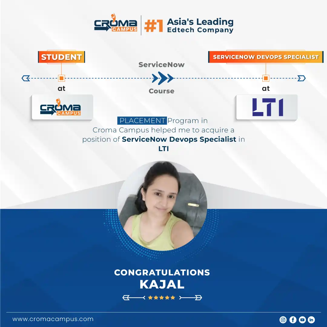
+91-971 152 6942Stories
success
inspiration
career upgrade
career upgrade
career upgrade
career upgrade
You will get certificate after
completion of program
You will get certificate after
completion of program
You will get certificate after
completion of program
in Collaboration with
Empowering Learning Through Real Experiences and Innovation
we train you to get hired.
Phone (For Voice Call):
+91-971 152 6942WhatsApp (For Call & Chat):
+91-971 152 6942Get a peek through the entire curriculum designed that ensures Placement Guidance
Course Design By
Course Offered By
Ready to streamline Your Process? Submit Your batch request today!
SP3D (SmartPlant 3D) is a 3D CAD software specifically used for plant designing, piping, structural and equipment modeling. It is quite popular in engineering companies.
Yes, this course is suitable for both freshers and working professionals, especially if you want to make a career in Oil & Gas, Energy or Manufacturing sector.
Croma Campus offers live projects and internships as well as job assistance and interview preparation.
Yes, Croma Campus offers SP3D course in offline mode in Mumbai and online mode across India.
Yes, after completion of the course a recognized certificate is provided which is helpful for getting a job.
Highest Salary Offered
Average Salary Hike
Placed in MNC’s
Year’s in Training

fast-tracked into managerial careers.
Get inspired by their progress in the
Career Growth Report.
FOR QUERIES, FEEDBACK OR ASSISTANCE
Best of support with us
Share some of your details and we will be in touch with you for demo details, and know about Batches Available with us!

For Voice Call
+91-971 152 6942For Whatsapp Call & Chat
+91-9711526942Share some of your details and we will be in touch with you for demo details, and know about Batches Available with us!


 Career Transition
 Career Gap
 Placement Activities
 Placement Drives
 Latest Hiring


.webp)


.webp)
.webp)

.png)


